Frame Design of Engine Mount
Overview
Frame construction is used throughout the aerospace industry in the creation of welded steel-tube fuselages, piston-engine motor mounts, ribs, and landing gear. In this activity I design a frame assembly for a motor mount structure for a Lycoming O-300 to be installed in a light aircraft.
Equipment
Computer with Autodesk® Inventor® installed and access to the internet.
Procedure
The frame must meet the constraints shown below.
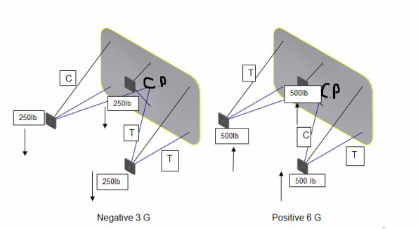
- The large plate represents the aircraft firewall as shown in the image below. This must be grounded as the stable part of the frame. Use fixed constraints on the six firewall to structural member attachment point.
- The structure will support one Lycoming O-300 engine (250 lb) attached at the three points indicated.
- The structure will be loaded with negative 3 G and positive 6 G which is simulated by exaggerated engine weight.
- The structural members will be 1 ½ in. ANSI pipe.
- Frame members should be mitered as necessary

Design
This is the model made from Autodesk Inventor.

This shows the negative 3 G with my first try of simulation compared to the fixed constraint change in the second picture. The change in fixed constraints improved the overall strength in compression and tension.

The screen capture below shows the strength with positive 6 G.

Weight and Cost

Design Benefits
My design for the frame is different because of type of pipe I used and the placement of the six constraints. The material I used is "Pipe Extra Strong" which will be more expensive and heavier, but will ultimately be more efficient for a longer lasting and much sturdier frame. The constraint I put on the bottom of the center piping, will lessen the support for that given part, but gives the needed support to the outside framing.
Conclusion Questions
1. Explain how the frame analysis showed that the critical area was different than the critical area that you predicted.
The frame analysis was able to highlight the parts of the piping that demanded the most support and show areas where the piping was secure. I thought the critical point did not vary and was the same for all forces exerted on the frame. The critical area turned out to be where a fixed constraint was not placed and is where pipes meet in the middle of the frame.
2. Explain what additional loading conditions that an aircraft designer needs to include as a constraint.
Other variables such as carrying weight capacity and the metals reaction to outside weather conditions will need to be considered. If the metal does not react well with precipitation, the frame will not hold up and will break. This is also true for the carrying weight. If the system is only made to hold a certain amount, putting more weight on will hold the risk of having the whole frame fail.
